
This small application is a protocol converter for the VFG-150 versatile frequency generator.
The VFG-150 is a frequency synthesizer for the frequency range from a few kHz to 150 MHz. It has been developped by Thilo Hannemann, at the time in the group of C. Wunderlich at the University of Hamburg, Germany. The synthesizer has been designed to allow very versatile user-defined modulations and sweeps instead of the relatively slow and unflexible frequency control options provided by established frequency synthesizers.
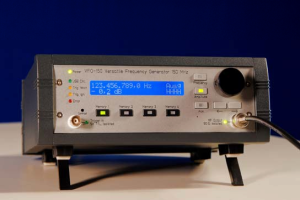
The device can change both amplitude, phase and frequency every 5 ns. For aritrary modulation, the device is remote-controlled over an USB2.0 link. With its internal buffer of approximately 1000 slots, e. g. 1000 slot frequency sweeps with 5 ns dwell time are possible, or, given the data rate of the USB 2.0 bus, continuuous sweeps with less than 50 ns dwell time are possible. Each step in a (phase,frequency,amplitude)-sequence can be indidividually triggered by a digital TTL signal and an external signal source. The synthesizer is not limited to a given dwell time / slot length; this can be specified for each individual slot in multiples of 5 ns.
This software (vfg-control) is a protocol translator for the VFG-150, released under the GPL. It was developped by Manuel Succo and Christian Ospelkaus at the University of Hamburg with the goal to make this device usable for quantum gas experiments, although the software can probably be used in many other scenarios and also serves as a simple c programming example for the VFG.
In many quantum gas experiments (and probably in many other physics / engineering applications), control software for the experiment supports ouput to devices controlled over a simple command language and interfaces such as GPIB, serial interfaces, parallel ports or network connections. An important example for a library allowing such connections to be used in e. g. Labview is the National Instruments VISA library.
In order to make the VFG controllable over VISA, we have developped this application which listens on a network port for incoming TCP connections, interprets a simple and extensible command language and sends corresponding binary data to the VFG over the USB link.
Since NI VISA supports, among the many other options mentioned above, arbitrary TCP/IP network connections, this is a very versatile approach for integrating the VFG-150 into an existing experiment. The following diagram illustrates the communication between experiment control system (your software), vfg-control, and VFG:
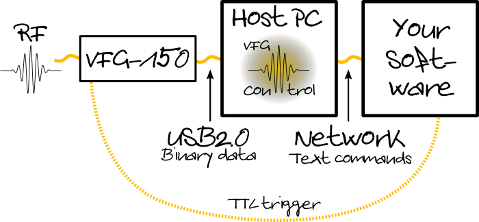
Of course, timing critical code sequences cannot rely on the timing of the network link. Therefore, a complex sequence can easily be preprogrammed over the network link and then triggered via a TTL line from your main control system. The vfg-control and your control application can, but do not have to run on the same host computer due to the flexibility of the network link.
To get you started, here is an example of code sent to the VFG over the network link which we have used:
aux 0;
amp -99.;
tri;
amp -20.;
swe 40. 5. 7000. .1;
swe 5. 1. 4000. .1;
swe 1. 0.503 2000. .1;
amp -99.;
tri;
aux 1;
amp 0.;
swe 142.7 142.3 10. .05;
aux 0;
amp -15.;
swe 7.7 6.83 40. .05;
amp -99.;
tri;
gep 80.0400  -31. 0.8 0.01;
amp -99.;
eos;
flush
This code first sets the four digital outputs at the back of the VFG to zero (aux 0;). The output amplitude is set to -99 dBm, effectively disabling the output. Then, the device will wait for a trigger on the TTL trigger line. Once this will have arrived, there will be three subsequent frequency sweeps, one from 40 to 5 MHz in 7000 ms with a 100 microsecond dwell time, one from 5 to 1 MHz in 4000 ms with a 100 microsecond dwell time and one last from 1 MHz down to 0.503 MHz in 2000 ms with also 100 microseconds dwell time. When the sweeps are over, the output is switched off again (amp -99.;). When the next external trigger pulse has arrived, the first digital ouput is set to 1, the amplitude is set to 0 dBm and another sweep is performed (from 142.7 MHz to 142.3 MHz in 10 ms with a dwell time of 50 microseconds). The digital ouput is switched off again, the amplitude is set to -15 dBm, and a linear sweep from 7.7 to 6.83 MHz is performed. The output is switched off again, and the next step starts with an external trigger. Once this arrives, the device produces a gaussian amplitude envelope pulse with a fixed frequency of 80.04 MHz which lasts for 800 microseconds (1/e2 amplitude half width of 200 microseconds) and is divided into slots of 10 microseconds length. After the pulse is over, the output is switched off. The eos; (end of sequence) command tells the VFG not to expect more data afterwards. The application only starts to interpret and execute the commands, however, once it receives the flush token.
For the specialist, here is what this is good for: the first three linear sweeps are for evaporative cooling. Switching the digital output of the VFG controls an rf multiplexer which sends the output of the VFG into a mixer where it is mixed with a fixed frequency in the vicinity of 6.8 GHz. So the next sweep is a Rapid Adiabatic Passage (RAP) transfer of 87Rb from the F=2,mF=2 to the F=1,mF=1 state at the hyperfine splitting for those two states for a magnetic field of approximately 20 G. The output is then switched back to the regular rf amplifier, and with the 7.7 to 6.83 sweep, 40K is transffered from F=9/2,mF=9/2 to F=9/2,mF=-7/2. The Gaussian pulse is used for rf spectroscopy on the 40K F=9/2,mF=-7/2 to F=9/2,mF=-9/2 transition for magnetic fields close to 547 G. If you want to learn more about this, read Physical Review Letters 97, 120402 (2006) or Christian's PhD thesis.
Contact and support: ospelkau at users.sourceforge.net